
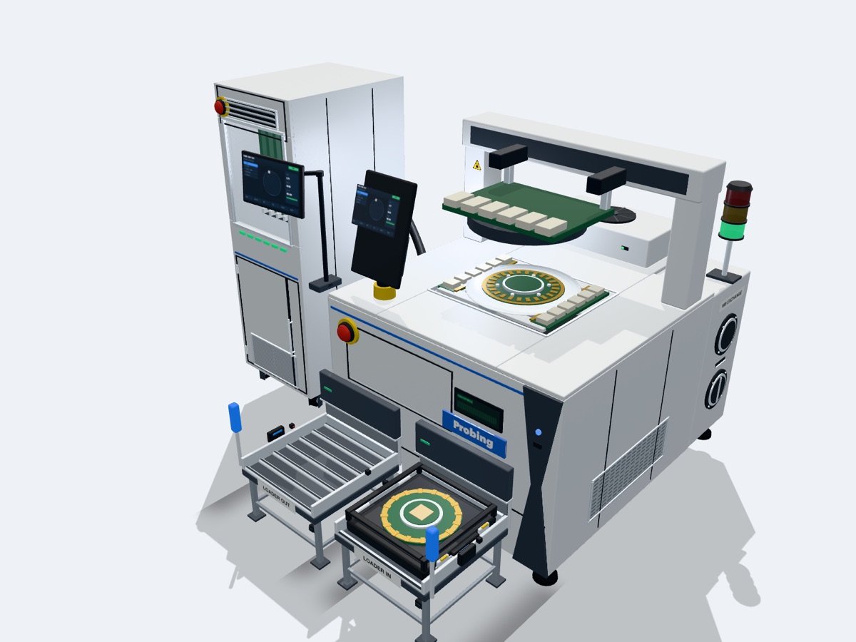
 Test and validationPCT5801 · DeepTouch1000 · motherboards · PSTA20K
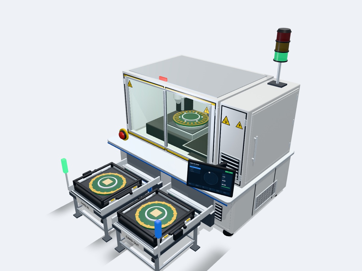 Probe assemblyProbe placement and laser micro-welding
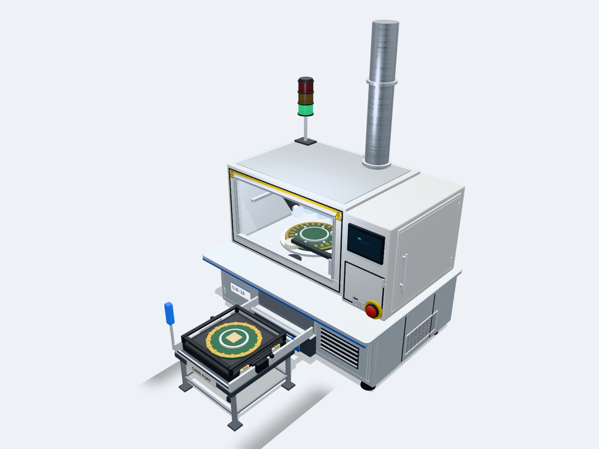 Cleaning and reinspectionCleaning and three-direction reinspection
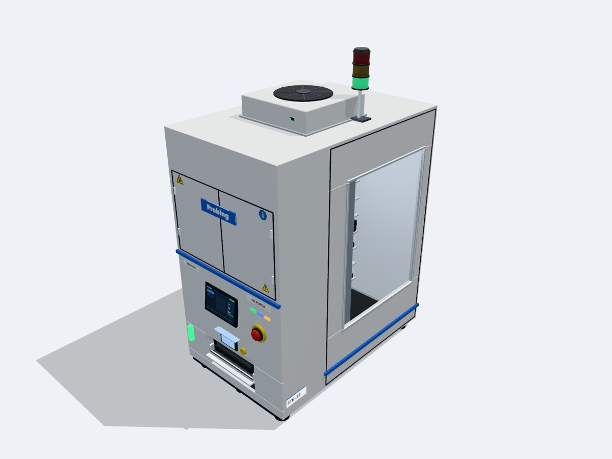 Smart storageStorage and traceability
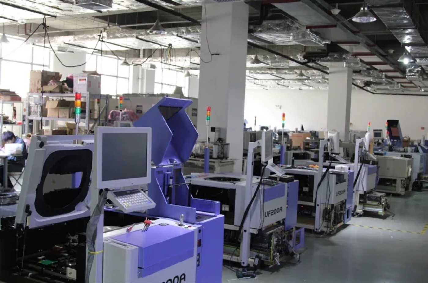 Prober servicesInformation box · uP200A · pre-owned equipment
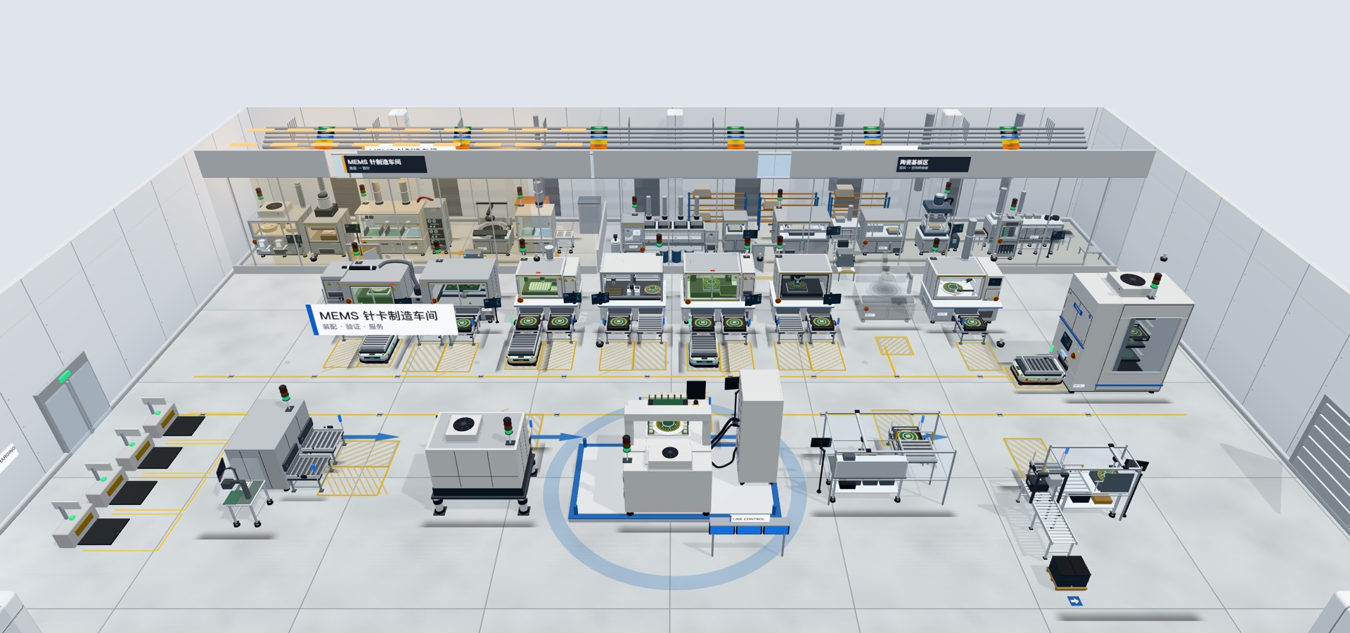 Probe-card hallMEMS probe-card manufacturing and validation · 21 stations
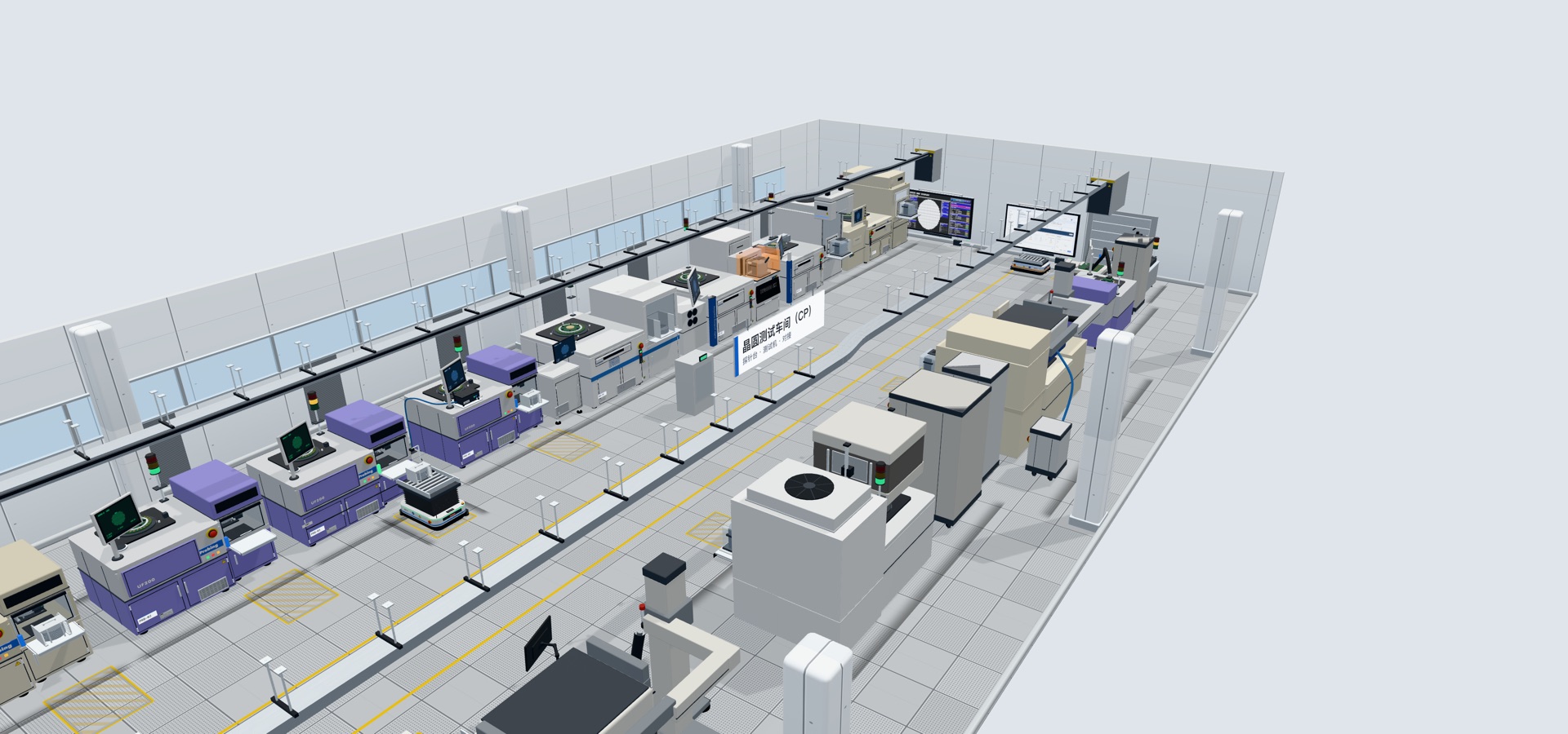 CP hallProbers, tester docking and retrofits of installed probers · 17 stations
Terms and definitions
Channel counts, pin counts, scan paths and chuck force each have a definition and conditions; they are set out here one by one.
Glossary
Channels and pins
Card-side pin countThe number of physical pins on the probe card, set by the device under test.
The card-side pin capacity of the current PCT5801 platform is 67,000 pin. This number counts the pins on the card and is not the same quantity as the number of tester channels.
For the same whole-wafer touchdown, the pin count differs by almost twenty times from NAND and NOR to DRAM and HBM. The device sets the pin count.
Matrix scan pathsIndependent paths the relay matrix can switch through in turn; the PCT5801 limit is 65,536.
The PCT5801 relay matrix has 1,024 channels per board and up to 64 boards, addressing 65,536 nodes. Nodes are switched in turn, not connected at the same time.
67,000 is the card-side pin capacity and 65,536 is the limit of independent scan paths; they are different quantities. The mapping from physical pins to scan paths is designed per card type.
The PSTA20K socket tester uses the same basis: 16,384 is the relay matrix architecture limit, and the output is matrix scan paths, which does not equal the socket pin count.
Tester channelsThe number of electrical signals on the tester side; not the same as the probe card pin count.
PCT5801 has 16,384 channels as standard and 65,536 at maximum configuration, referring to matrix-scanned test paths. The channel count in a specification cannot be read directly as a pin count.
Channel capacity is organised as a relay matrix of 1,024 channels per board and expands with card type and rack configuration. The final channel count is fixed during sample evaluation, the technical agreement and FAT / SAT.
Simultaneous instrument resourcesThe instrument units actually measuring at the same moment; they depend on the instruments fitted.
This means the PMU, DPS and digital units measuring at the same moment. Matrix nodes are switched in turn, and the resources measuring at the same time are set by the units fitted.
PCT5801 ATE resources are 256 pin / unit, up to 4 units, configured for the target card type and test items. The number of simultaneous resources cannot be derived from the channel count or the pin count.
Fan-outA small number of test channels expanded stage by stage, through a relay matrix and motherboard, to a large number of contact points.
The front end of PSTA20K is the 256 test channels of the Advantest EVA100. They fan out stage by stage through a relay matrix and a motherboard customised for the socket, spreading over several thousand to more than ten thousand contact points.
Fan-out and scan method are set by the pin map, and results are output point by point according to the pin map.
Touchdown and load
Chuck forceThe force the prober chuck provides when the whole card is pressed.
The chuck force of DeepTouch1000 is 1,000 kgf (about 9.81 kN), measured at full load. Chuck force is displayed in real time during touchdown.
High-pin-count cards are limited by chuck force on probers such as the UF3000 / UF3000ex and P-12XL. DeepTouch1000 was therefore developed for 1,000 kgf.
Chuck force is the force the machine delivers. How much force simultaneous whole-card contact needs is shown under Representative calculation.
Measured at full loadLoaded in steps to 1,000 kgf while straightness, flatness and tilt are measured.
The DeepTouch1000 chuck force is loaded in steps to 1,000 kgf while Z-axis straightness, chuck flatness and tilt are measured. The three loading runs gave consistent results, with a symmetric structure and no asymmetric deformation.
- Z-axis straightness · 0 ~ 1,000 kgf
- < 0.2µm
- Chuck flatness deviation · 3 mm stroke
- ≤ 10µm
- Tilt · about 16.2 µm across D300 mm
- ≈ 0.003°
Representative calculationEstimates the touchdown force a whole card needs under assumed conditions; the result is an estimate.
The touchdown force needed for simultaneous whole-card contact of a high-pin-count card is estimated at about 450 kgf under representative conditions. Method: number of pins in simultaneous contact × target contact force per pin. A single pin is assumed at 1.5 gf.
- Target contact force per pin · assumption
- 1.5gf
- Whole-card touchdown force · representative estimate
- ≈ 450kgf
- Chuck force · measured at full load
- 1,000kgf
450 kgf is an estimate and 1,000 kgf is a value measured at full load. The actual total load depends on the number of pins in simultaneous contact, force per pin, overdrive and safety factor. Card structure, contact travel and process conditions also affect the total load.
Status and supply
Product statusOnly three words are used: In production, Engineering stage, In development.
In productionEquipment supplied in volume production; capability is as stated on the product page.
Engineering stageEquipment and in-house projects at the engineering stage. For pin assembly and laser micro-welding equipment, for example, placement accuracy and UPH are determined by sample trials. No cross-customer figure is committed publicly.
In developmentProjects in the design stage, the concept stage, as engineering prototypes or under development are all marked In development. For ECP1010, for example, specifications follow design iterations and there is no volume delivery record yet.
Supply boundaryWhich steps on the chain are covered by Probing equipment and which are handled by specialist suppliers.
Of the 21 stations in the probe-card hall, 4 are in production, 4 are in the engineering stage, 1 is in development, and the remaining 12 are handled by specialist suppliers. Upstream MEMS probe fabrication and multilayer-ceramic space transformer making are drawn in the diagram so that the chain is complete.
Probe manufacturing, incoming sorting, space transformer and PCB manufacturing, guide plate machining, card body assembly, shipping packaging and re-pinning are handled by specialist suppliers. Equipment for these steps is outside Probing's scope of supply.
The boundary is drawn at the specific step: cleaning equipment only marks a card as needing rework, test equipment only retests after repair, and the storage system ends at issue within the plant and handoff downstream.
Third-party modelsMaker model names are used only to define the range of machines we can take on.
Maker model names such as UF200, UF3000, P-12XL and V93000 are used only to define the range of machines we can take on. Mentioning them does not indicate authorisation, certification or endorsement by those makers. Retrofit and rebuild work is carried out by Probing, which takes responsibility for it.
Advantest EVA100 is an Advantest product; Probing is its representative and distributor and is responsible for mechanical integration, application engineering and test program development. Apart from this representation, mentioning a maker's name does not indicate any authorisation or endorsement.
These models carry no product status; they are described as refurbished supply, retrofit or service, according to the facts.
Basis and delivery
Evidence gradeThe small print under a number: whether it is measured, rated, configured or a design basis.
Specifications, times and capability figures on this site state their basis and evidence grade, for technical assessment. The common forms are:
- Measured at full load: measured under full-load conditions, for example chuck force 1,000 kgf.
- Standard / maximum configuration: the standard configuration delivered and the configurable upper limit, for example 16,384 and 65,536 channels.
- Stated in documentation: the value comes from material such as the product catalogue, and on site the measured value governs, for example uP200A overall accuracy 5 µm.
- As-of date: figures that change carry a date, for example 30 systems installed (as of August 2026).
- Design-document basis: products in development are described from design documents, and specifications follow design iterations.
Depth of public informationThe website gives capability headlines and evidence grades; configuration details are provided per project.
Product pages give capability headlines and evidence grades. Module specifications, task times and delivery configuration details are provided per project.
Published parameters are subject to the project's technical documents and the final acceptance scope.
Technical agreementStates the configuration, measurement method, thresholds, takt, data interfaces and the responsibilities of both parties.
The technical agreement comes after sample evaluation and before FAT. Sample evaluation first confirms the object, interfaces, current state, failure modes and samples usable for validation.
For a formal project, the technical agreement confirmed by both parties governs.
FAT / SATFactory and site acceptance, confirmed item by item with real samples.
FAT, factory acceptance, uses the agreed samples to verify function, repeatability, reports and exception handling. SAT, site acceptance, completes on-site integration, training, upstream and downstream interfaces and closure of open items.
The order is sample evaluation → technical agreement → FAT → SAT. Fixtures, algorithms, thresholds, repeatability and task times are confirmed item by item with real samples in FAT / SAT.
Test and interfaces
Leakage criterionThe threshold for judging leakage in all-pin-to-pin test; 10 nA on PCT5801.
The PCT5801 leakage current test is an all-pin-to-pin test with a criterion of 10 nA.
The criterion and the current resolution are two different quantities. The 0.1 nA stated for PSTA20K is the current resolution on the 500 nA range.
TDRAn AC test that measures transmission time on signal channels.
The PCT5801 PBDATA test measures transmission time (TDR) on all signal channels; task time depends on pin count and configuration.
TDR on the original platform requires controlled motherboard trace length and impedance. The T5833 FULL configuration motherboard already supports both DC and TDR test. AC test on the other platforms is customised case by case under ODM requirements.
MotherboardThe board between the probe card and the tester; it sets how the card is pressed and how signals are routed.
Mechanically, the motherboard determines how the probe card is pressed, aligned and loaded. Electrically, it determines how long the signal runs, how impedance is controlled and how many channels can be brought out.
The PCT5801 end-to-end path is ATE → relay matrix → motherboard → probe card; if any link is mismatched, whole-card test cannot be completed.
ZIF / POGOThe contact interface form between the motherboard and the probe card.
When PCT5801 and DeepTouch1000 form the combined cell, the card is loaded on the top head plate and the motherboard presses against it through a ZIF / POGO contact ring.
The pressing structure is a Bridge Beam, and the interface form is designed for the customer's card type.
Traceability and plant systems
Card IDThe identity number of a probe card; cleaning and storage records are filed by card number.
Before cleaning, Card ID / RFID is read to confirm card type, contamination location and the permitted cleaning method. Card number, recipe, number of cleans, images, judgement and personnel are recorded per card.
On receipt, the storage system reads or binds the RFID and checks card number, status, cleaning / test result and the target location.
RFIDThe tag that identifies a card, linking card number, location, status and movement history.
After a card is bound to its identity by RFID, it is stored in an environment-controlled location. RFID records card identity, location, status, movements and inventory counts.
Frequency band, tags, read range and anti-cross-read are determined by on-site trials.
WMS / EAP / MESPlant-side systems: they dispatch tasks to equipment and receive status and records back.
The smart storage system receives put-away, issue, return and inventory tasks dispatched by WMS / EAP / MES, and returns status, exceptions and audit records. Fields, permissions, heartbeat, retry, compensation and audit follow the interface protocol.
When older probers such as the UF200 and UF3000 left the factory, production lines had no MES or EAP connection requirement. The information box marks the status hop by hop along EAP / MES → HSMS → GEM → machine, so a wrong connection shows up before go-live.
Data source gradeThe origin of the data, marked on every page of the prober information box.
Grades are live, machine configuration snapshot, local configuration, offline and design reference. Reference-grade pages disable interaction automatically.
For example, wafer geometry is read from the snapshot of the machine configuration card, and test counts are read from the machine run memory and marked live. A page whose source is not connected locks automatically; inferred values do not replace measured ones.
Related
Give the engineering team the card type, interfaces and targets
We will acknowledge receipt within one business day.