
The board between the card and the tester
Probe Card Motherboards
When a probe card will not run on a tester, the problem is often neither the card nor the machine but the motherboard between them. It does two jobs at once: mechanically it sets how the card is pressed, aligned and loaded; electrically it sets trace length, impedance control and how many channels actually come out. Probing designs and builds them as ODM for the tester platform and the target card, delivering the contact structure and the routing together.
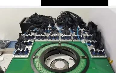
A motherboard in the shop: probe card contact area at the centre, channel harnesses grouped around it. Interface and quantity depend on platform and card type.
The same points in words
- Platforms
- Mainstream memory and SoC testers
- Highest channel count
- The V93000 configuration
- Test coverage
- AC available on the T5833 FULL configuration
- Delivery model
- Designed and built per platform and card
Equipment and engineering solution
Applications
Designed for the following probe card manufacturing, test and maintenance tasks.
A new card on an existing tester
Channel expansion
Adding AC test
Isolating a contact failure
The same points in words
- A new card on an existing tester
- Rebuild the motherboard around the card's contact scheme and signal definition.
- Channel expansion
- Moving from 8 TOM to 32 TOM or FULL, the motherboard decides how many channels actually come out.
- Adding AC test
- TDR transfer-time measurement on an existing platform depends on controlled trace length and impedance in the board.
- Isolating a contact failure
- Verify the motherboard on its own when contact resistance rises or channels drift, instead of suspecting the probe card by association.
SPECIFICATIONS
Specifications
The final configuration follows the card, interfaces, site conditions and acceptance items.
See the full specification table
| Item | Specification / configuration | Notes |
|---|---|---|
| Contact and routing | Stable contact structure with low-resistance routing | Contact resistance and signal integrity are the board's two basic measures |
| Other platforms | Boards for T2000, 93K-DD and UltraFlex are assessed per project | A platform outside the delivered list needs a feasibility check first |
WORKFLOW
Workflow
01 Confirm platform and card
02 Structure and routing design
03 Build and assemble
04 Verify electrically, then deliver
The same points in words
- Confirm platform and card
- Fix the tester model, the TOM / FULL configuration, and the card's contact structure and signal definition.
- Structure and routing design
- Set the contact structure, contact element type, layer count and impedance targets.
- Build and assemble
- Machine the board, fit the contact elements, and check mechanical fit against card and test head.
- Verify electrically, then deliver
- Run opens, shorts, contact resistance and, where required, TDR on PCT5801 before delivery.
FAT / SAT
Project delivery
Sample evaluation
Technical agreement
FAT
SAT
The same points in words
- Sample evaluation
- Confirm the object, interfaces, current state, failure modes and available validation samples.
- Technical agreement
- Define configuration, measurement method, limits, takt, data interfaces and responsibilities.
- FAT
- Verify functions, repeatability, reporting and exception handling with agreed samples.
- SAT
- Complete site integration, training, upstream/downstream interfaces and issue closure.
CONFIGURATION
Configuration and acceptance
System configuration, optional items and acceptance conditions are summarized below.
Delivered configurations
8 TOM and 32 TOM for Advantest T5830, FULL for T5833, SSV / XV for Teradyne M5 and the 4,000-pin configuration for Advantest V93000 have all been designed, built and delivered.
Where AC stands today
The T5833 FULL board carries both DC and TDR AC test. On the other platforms AC is built to order as ODM, not an off-the-shelf capability.
Production deployment
Boards are in production use at several wafer fabs. Customers, unit counts and projects are not disclosed.
Position in the test path
The PCT5801 path runs ATE, relay matrix, motherboard, probe card. A mismatch at any of the four stops whole-card testing, and the motherboard is the link most often underestimated.
Share the card, interfaces and target
Send the sample, installed equipment, current issue and target takt. We will acknowledge receipt within one business day.