
A test system, not a probe card analyzer
PCT5801 Probe Card Test System
PCT5801 sits between the ATE and the probe card, forming an end-to-end test path across full-function ATE, relay matrix, motherboard and card. It reproduces the project's specified tester electrical resources, motherboard routing and control-resource conditions rather than performing static resistance measurement alone, which is why it covers open, short, nA-level leakage, control resources and TDR transfer time.
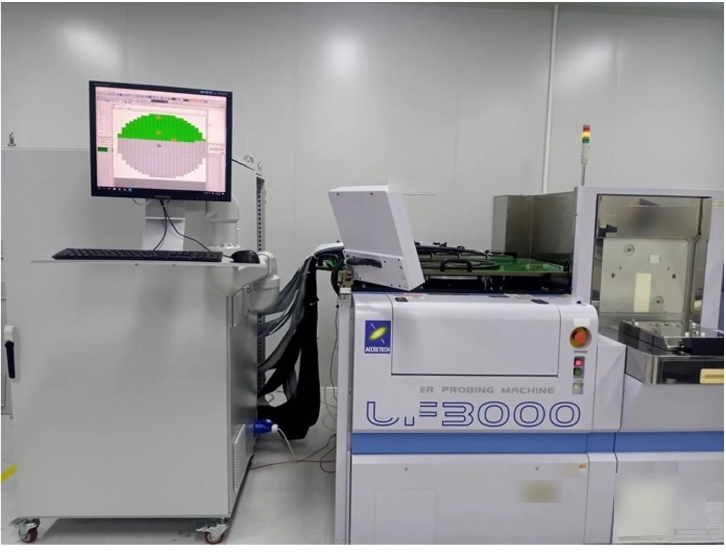
Photographed on site: the PCT5801 tester cabinet beside the prober, with the whole-wafer result on the adjacent screen.
The same points in words
- Card-side pins
- Current platform capacity; v2 architecture target 300,000
- ATE resources
- Full-function ATE front end
- Relay matrix
- Modular channel expansion
- Card interface
- Bridge Beam contact structure
Equipment and engineering solution
Applications
Designed for the following probe card manufacturing, test and maintenance tasks.
Release and post-repair test
Pre-ATE interface validation
High-channel expansion
The same points in words
- Release and post-repair test
- Check opens, shorts, leakage and control resources with a traceable report.
- Pre-ATE interface validation
- Verify motherboard, channel and basic electrical state before occupying a production tester.
- High-channel expansion
- Organize capacity around 1,024-channel modules and scale for the card and rack configuration.
SPECIFICATIONS
Specifications
The final configuration follows the card, interfaces, site conditions and acceptance items.
See the full specification table
| Item | Specification / configuration | Notes |
|---|---|---|
| Configurable resources | Control, source-measure, digital, waveform and capture modules selected per test item | Module specifications are provided in the technical agreement |
| Virtual instruments | Source and measure, digitizer, scope and spectrum analysis, pin-map visualisation | Software instrument panels |
| Operator interface | Graphical, customisable GUI | Test flow and display adapt to customer practice |
| What a channel means | Channel counts are electrical signals on the tester side, not probe-card pins | Keeps channel counts from being read as pin counts |
| Digital capability | 16,384 channels standard; 65,536 maximum configuration (matrix-scanned test paths) | Channels are tester-side scanned signals, not probe-card pins; concurrent instrument resources follow the fitted units |
| Software tools | Graphical sequence programmer, digital vector editor and debugger, logic analyser, virtual instrument panels, shmoo debugger, automatic VI-curve reports | Supplied with the system |
| Data and reports | The recipe system supports reuse and archiving, with automatic report generation | Data interfaces are agreed in the technical agreement |
| Site conditions | Air cooled; 15 to 30 °C, 30 to 70 % RH; AC 220 V 50/60 Hz | Nominal for the base configuration; varies with configuration |
WORKFLOW
Workflow
01 Open test
02 Short test
03 Leakage test
04 Control test
The same points in words
- Open test
- Continuity across all channels with every pin open
- Short test
- All pins on a short plate to detect channel-to-channel shorts
- Leakage test
- All pin-to-pin measurement against a 10 nA test threshold
- Control test
- MCW / FPGA / ASIC / I²C / SPI control-resource verification
EVIDENCE
The machine and its results

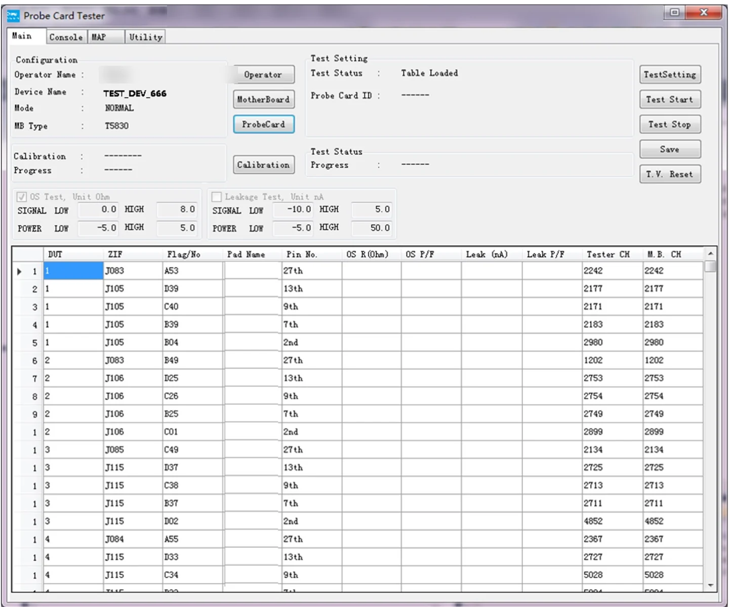
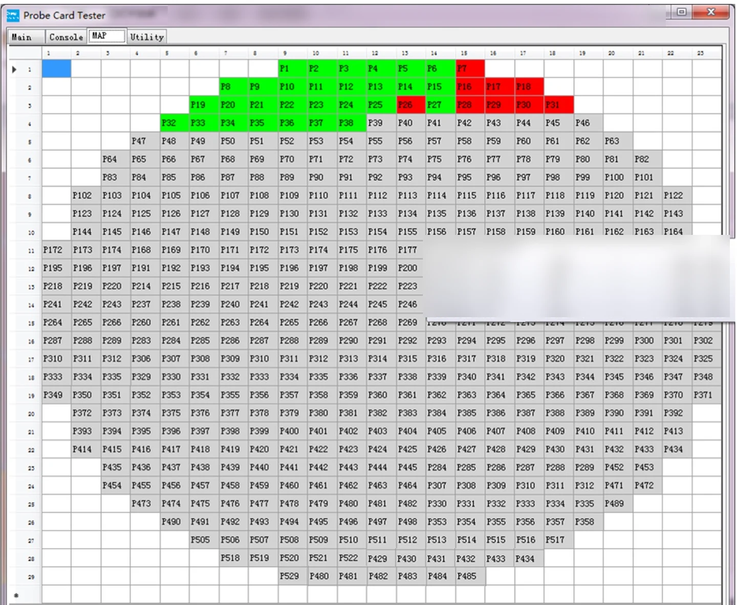
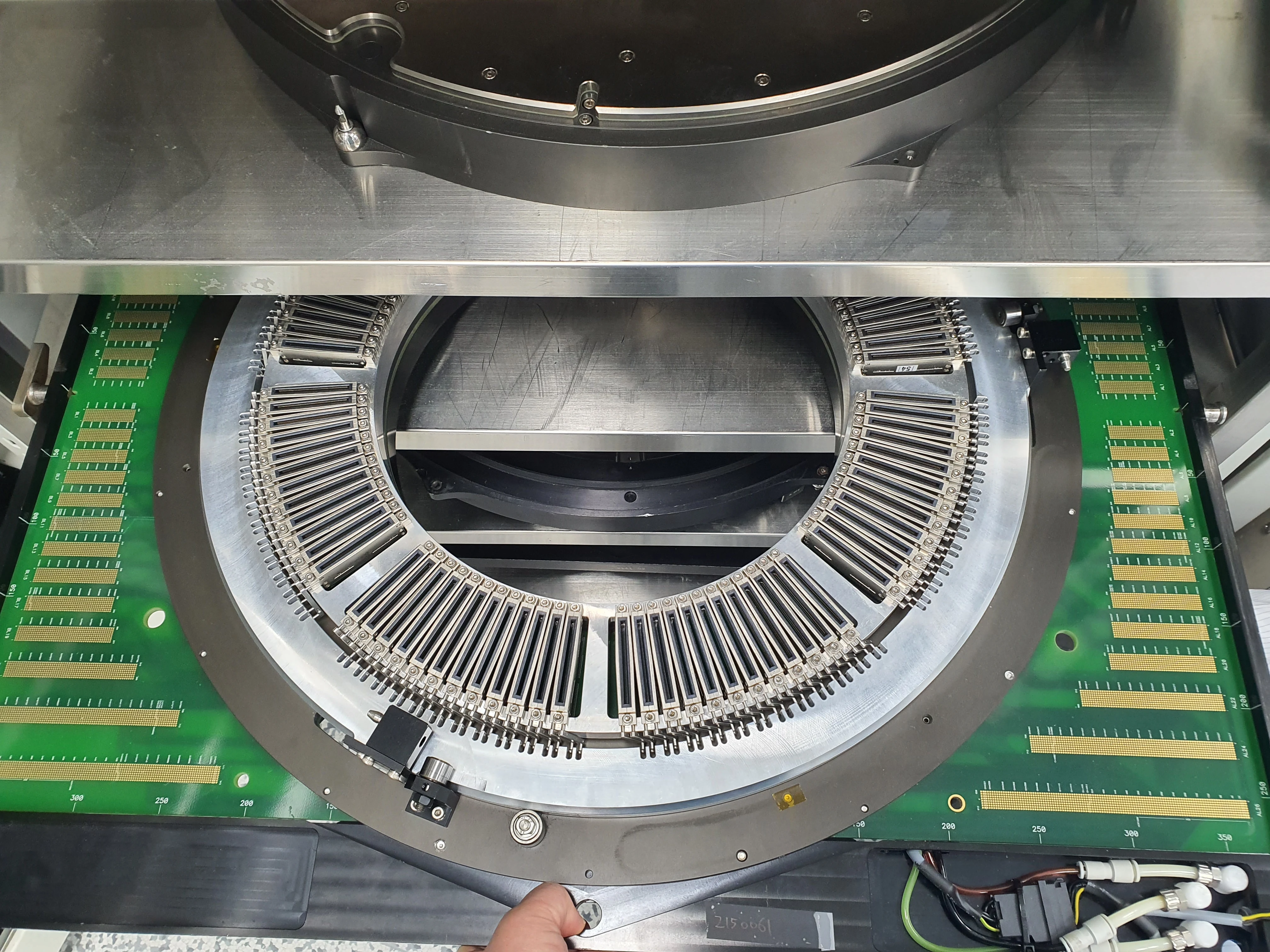
FAT / SAT
Project delivery
Sample evaluation
Technical agreement
FAT
SAT
The same points in words
- Sample evaluation
- Confirm the object, interfaces, current state, failure modes and available validation samples.
- Technical agreement
- Define configuration, measurement method, limits, takt, data interfaces and responsibilities.
- FAT
- Verify functions, repeatability, reporting and exception handling with agreed samples.
- SAT
- Complete site integration, training, upstream/downstream interfaces and issue closure.
CONFIGURATION
Configuration and acceptance
System configuration, optional items and acceptance conditions are summarized below.
Adapted tester platforms
Solution adapted and delivered: Advantest T5830 (440/480), T5833 (520), V93000 and Teradyne Magnum 5. Solution in build: Advantest T5221, CCTech C16/P16/P16+, Teradyne UltraFlex. Solution planned: XB1152, TM8000, SM0X00, M7, T5825.
AC test
The PBDATA test measures transfer time (TDR) across all signal channels; task times follow pin count and configuration and are agreed in the technical agreement.
Capability position
Covers DC, TDR, logic control and mechanical inspection within one system architecture, orchestrated per the ATE, relay-matrix and instrument configuration; general probe card analyzers usually cover only part of this.
Where it has been shown
Shown as a working machine at Semicon China (Shanghai), Semicon Southeast Asia (Singapore) and SWTest (US) in 2025.
Vendor-neutral
The system is configured around each customer's tester, motherboard, probe card and factory interfaces, tied to no single probe-card maker or ATE platform; quality, cost and lead time are set by contract.
Pins versus scan paths
The mapping from card pins to matrix scan paths is designed per card type; 67,000 is the card-side pin-capacity figure and 65,536 the independent scan-path ceiling - different quantities. The PCT5801v2 architecture extending toward 300,000 pins is presented in technical discussions.
Depth of this page
This page carries capability headlines with their evidence tiers; module specifications, task times and delivered-configuration detail are provided in the technical agreement.
Share the card, interfaces and target
Send the sample, installed equipment, current issue and target takt. We will acknowledge receipt within one business day.