Pick · align · weld · closed-loop verification
MEMS Probe Card Pin Assembly and Laser Micro-Welding
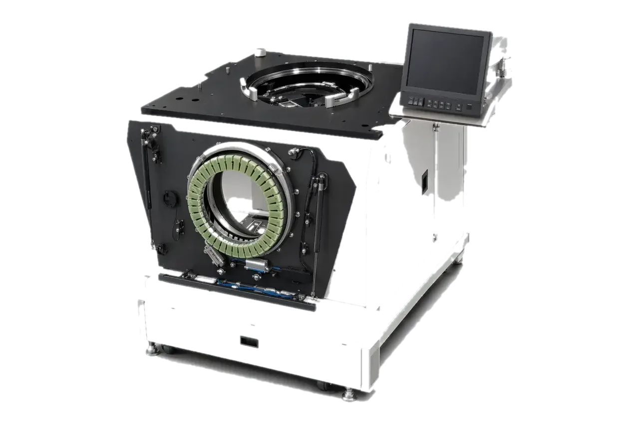
The station is configured around the probe, substrate, fixture and datum. Each probe passes three gripper handovers - pick, alignment and weld - before laser micro-welding, and an autofocus check confirms position afterwards. What actually decides yield is not the weld itself but whether a defect can be caught immediately after: that step is handled by PCT5801 electrical test and DeepTouch1000 whole-card touchdown validation.
Category visual for probe card assembly equipment. The actual pick, alignment and laser micro-welding stations are designed per probe type, card type and sample.
The same points in words
- Process chain
- Three gripper handovers
- Joining
- Joint condition confirmed by vision
- Post-weld check
- Confirms weld position and contact face
- Closed loop
- Electrical and whole-card mechanical re-verification
Equipment and engineering solution
Applications
Designed for the following probe card manufacturing, test and maintenance tasks.
New card introduction
Manual-process standardization
Post-assembly quality loop
The same points in words
- New card introduction
- Establish process windows and fixture design from probe type, substrate and datum.
- Manual-process standardization
- Turn operator-dependent steps into recipes, images, judgements and exception records.
- Post-assembly quality loop
- Relate AOI, XYZ, probe height/force and electrical results to the assembly lot.
SPECIFICATIONS
Specifications
The final configuration follows the card, interfaces, site conditions and acceptance items.
See the full specification table
| Item | Specification / configuration | Notes |
|---|---|---|
| Recipe and traceability | Work order, material, operator, recipe version and result | Supports version traceability and review |
| Post-assembly validation | AOI, probe-tip XYZ, Pin Force and electrical checks | Combination selected by acceptance method |
| Safety | Motion limits, fixture interlock and fault stop | Confirmed by equipment risk assessment |
WORKFLOW
Workflow
01 Pick
02 Align
03 Weld
04 Verify
The same points in words
- Pick
- The pick gripper takes the probe from the tray and seats it against the alignment datum Avoiding added distortion during handover is the precondition for accuracy
- Align
- The alignment stage clamps and corrects probe attitude Gripper coplanarity and perpendicularity are the critical assembly metrics
- Weld
- The weld gripper transfers the probe and laser micro-welding runs Joint consistency controlled by vision and recipe
- Verify
- Autofocus position check, then PCT5801 and DeepTouch1000 Locates weld problems while still at the assembly stage
FAT / SAT
Project delivery
Sample evaluation
Technical agreement
FAT
SAT
The same points in words
- Sample evaluation
- Confirm the object, interfaces, current state, failure modes and available validation samples.
- Technical agreement
- Define configuration, measurement method, limits, takt, data interfaces and responsibilities.
- FAT
- Verify functions, repeatability, reporting and exception handling with agreed samples.
- SAT
- Complete site integration, training, upstream/downstream interfaces and issue closure.
CONFIGURATION
Configuration and acceptance
System configuration, optional items and acceptance conditions are summarized below.
Process parameters
Placement accuracy and UPH are determined by sample trials on the target probe, substrate and fixture; no universal cross-customer figure is published.
Closed-loop capability
PCT5801 covers post-weld electrical verification and DeepTouch1000 covers whole-card touchdown and 3D tip inspection, so anomalies trace back to a specific probe position.
Deliverables
Fixtures, algorithms, takt and the post-inspection combination are written into the technical agreement and verified at FAT/SAT.
Share the card, interfaces and target
Send the sample, installed equipment, current issue and target takt. We will acknowledge receipt within one business day.