
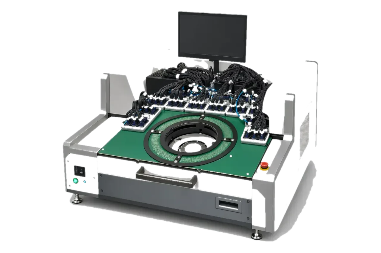
High-channel electrical and physical validation
Memory Probe Card Test System
Built for NAND, NOR, DRAM and HBM probe cards, the system connects PCT5801 electrical testing, tester/prober interfaces and DeepTouch1000 physical inspection in one flow for post-build, post-repair and high-pin-count release checks.
PCT5801 high-channel system. The current configuration supports 16,384 channels; motherboard and interfaces are designed for the target card.
The same points in words
- Standard configuration
- Tester channels as standard; 65,536 maximum
- Leakage test
- Range and limits set for the card
- Typical task time
- Task times follow pin count and configuration, agreed in the technical agreement
- System route
- Links electrical results with tip, load and contact state
Equipment and engineering solution
Applications
Designed for the following probe card manufacturing, test and maintenance tasks.
Memory probe card release
HBM and one-touchdown evaluation
Electrical anomaly localization
The same points in words
- Memory probe card release
- Build a traceable result set around Open, Short, Leakage, control resources and interface checks after manufacture or repair.
- HBM and one-touchdown evaluation
- Review channel organization and one-touchdown paths around the high-pin-count motherboard and tester/prober ecosystem.
- Electrical anomaly localization
- Locate open, short, leakage or control anomalies, then use tip XYZ, load and contact evidence to investigate physical causes.
SPECIFICATIONS
Specifications
The final configuration follows the card, interfaces, site conditions and acceptance items.
See the full specification table
| Item | Specification / configuration | Notes |
|---|---|---|
| Tester ecosystem | T5830, T5833, M5 and V93000 P16 | Interfaces follow the on-site tester, motherboard and project documents |
| Prober ecosystem | UF3000 / UF3000ex and the TEL P-12XL | Mechanical, electrical and automation interfaces are confirmed per project |
WORKFLOW
Workflow
01 Model samples and interfaces
02 Run electrical tests
03 Correlate physical checks
04 Report and retest
The same points in words
- Model samples and interfaces
- Confirm card type, pin count, tester, prober, motherboard, control resources and acceptance items.
- Run electrical tests
- Execute Open, Short, Leakage, MCW, control and selected high-speed items while retaining raw results.
- Correlate physical checks
- Inspect probe-tip XYZ, load, probe mark or contact state at anomalous locations.
- Report and retest
- Retain configuration versions, results, disposition and retest conclusions for FAT/SAT.
FAT / SAT
Project delivery
Sample evaluation
Technical agreement
FAT
SAT
The same points in words
- Sample evaluation
- Confirm the object, interfaces, current state, failure modes and available validation samples.
- Technical agreement
- Define configuration, measurement method, limits, takt, data interfaces and responsibilities.
- FAT
- Verify functions, repeatability, reporting and exception handling with agreed samples.
- SAT
- Complete site integration, training, upstream/downstream interfaces and issue closure.
CONFIGURATION
Configuration and acceptance
System configuration, optional items and acceptance conditions are summarized below.
Installed base
30 systems installed as of August 2026, across mainland China and Korea.
Expansion design
16,384 channels is the standard configuration and 65,536 the maximum. 60k DRAM / 300k HBM systems are designed around the target card, motherboard and tester interface.
Project definition
Final channel count, range, limits, interfaces and task time are set through sample evaluation, project documents and FAT/SAT.
Share the card, interfaces and target
Send the sample, installed equipment, current issue and target takt. We will acknowledge receipt within one business day.