
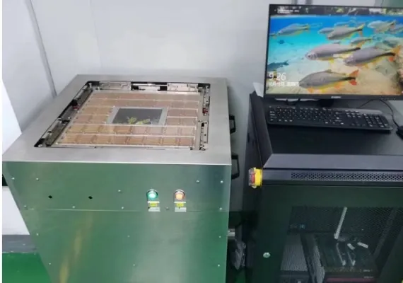
EVA100 plus relay matrix · beyond 5,000 channels
PSTA20K Ultra-High-Channel Socket Tester
A socket holds no die, so the only way to find the one bad contact is to put current through every one of them. PSTA20K uses an Advantest EVA100 to supply 256 test channels, then fans them out through a relay matrix and a socket-specific motherboard to thousands or tens of thousands of contacts, clearing open, short, leakage and per-pin contact resistance before a processor is ever installed. It is a derivative of the PCT5801 probe card test platform and shares the same channel-expansion and measurement architecture.
Category visual for socket test equipment. The actual motherboard, fixture and pin map are designed per socket sample.
The same points in words
- Test front end
- 256 channels
- Fan-out
- Architectural ceiling 16,384 outputs
- Measurement resources
- Concurrent resources are agreed in the technical agreement
- Current resolution
- On the 500 nA range
Equipment and engineering solution
Applications
Designed for the following probe card manufacturing, test and maintenance tasks.
Incoming and pre-assembly inspection
Fixture/socket development
Failure localization and retest
The same points in words
- Incoming and pre-assembly inspection
- Identify open, short or contact anomalies before an expensive processor is installed.
- Fixture/socket development
- Compare structures, compression conditions and contact networks.
- Failure localization and retest
- Localize anomalies to pin positions and networks and preserve retest history.
SPECIFICATIONS
Specifications
The final configuration follows the card, interfaces, site conditions and acceptance items.
See the full specification table
| Item | Specification / configuration | Notes |
|---|---|---|
| Data | Pin map, configuration version, channel results, fault position and retest records | Feeds incoming, engineering and quality flows |
WORKFLOW
Workflow
01 Import the pin map
02 Configure motherboard and fixture
03 Run the channel test
04 Report and release
The same points in words
- Import the pin map
- Verify nets, pin positions, reserved pins and judgement rules The pin map drives fan-out and scan order
- Configure motherboard and fixture
- Set fan-out path, locating and compression around the socket structure The motherboard is designed and built by Probing
- Run the channel test
- Open, short, leakage and per-pin contact resistance per the project task Faults are located to a specific pin
- Report and release
- Output configuration, point-by-point results and retest records Supports the installation decision
FAT / SAT
Project delivery
Sample evaluation
Technical agreement
FAT
SAT
The same points in words
- Sample evaluation
- Confirm the object, interfaces, current state, failure modes and available validation samples.
- Technical agreement
- Define configuration, measurement method, limits, takt, data interfaces and responsibilities.
- FAT
- Verify functions, repeatability, reporting and exception handling with agreed samples.
- SAT
- Complete site integration, training, upstream/downstream interfaces and issue closure.
CONFIGURATION
Configuration and acceptance
System configuration, optional items and acceptance conditions are summarized below.
Architecture and specification
EVA100 front end, relay matrix fan-out, PMU and measurement ranges are taken from the Probing socket tester product documentation Rev 1.7 (2024-11-15).
Channel scale
16,384 is the architectural ceiling of the relay matrix. The product is positioned for beyond 5,000 channels, and the delivered configuration follows the socket pin map and motherboard.
Test time
Nominal test times are quoted per 5,000 channels and exclude load/unload and temperature settling. Actual takt is confirmed by measurement once the target pin map and limits are fixed.
Share the card, interfaces and target
Send the sample, installed equipment, current issue and target takt. We will acknowledge receipt within one business day.